Reference Grid
A reference grid gives every dimension a location such as D5, so whoever measures the part can find it on the drawing. The location appears in the inspection plan and the Dimension Editor.
Opening the Grid
- Open the dropdown at the top of the sidebar.
- Choose Reference Grid.
- Click Auto-Detect to detect the drawing’s grid, or Create Grid to draw one (below).
When you’re done, click Back to Ballooning.
Detecting the Drawing’s Grid
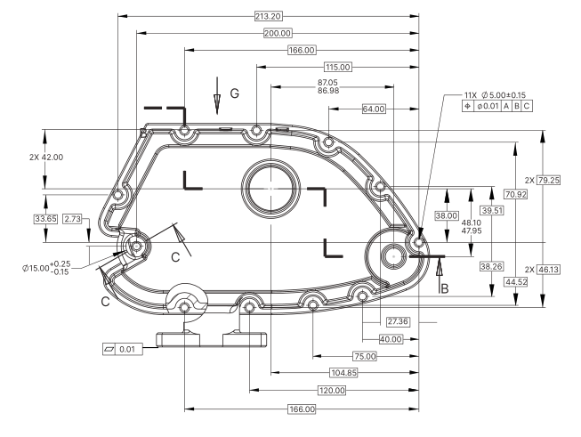
If the drawing has grid zones in its border, click Auto-Detect. Lens detects the zones and their labels: rows like F to A and columns like 8 to 1. Where the drawing has no labels, Lens generates them.
Creating a Grid Yourself
If the drawing has no grid, click Create Grid. A default grid appears over the drawing. Drag its lines to set the rows and columns.
Adjusting the Grid
- Resize all rows or columns: drag a grid line.
- Resize one row or column: click the lock icon next to its line to unlock it, then drag the line. The other rows and columns keep their size.
- Delete a row or column: click the × above its line. It merges into the column to its left, or the row below it.
- Relabel: change Row start and Column start in the sidebar, or pick a Label Scheme.
Removing the Grid
Click Remove Grid to delete the grid. This can’t be undone.
Grid Locations in Exports
Each location includes its page: 1-D5 is zone D5 on page 1, 5-C6 is zone C6 on page 5.